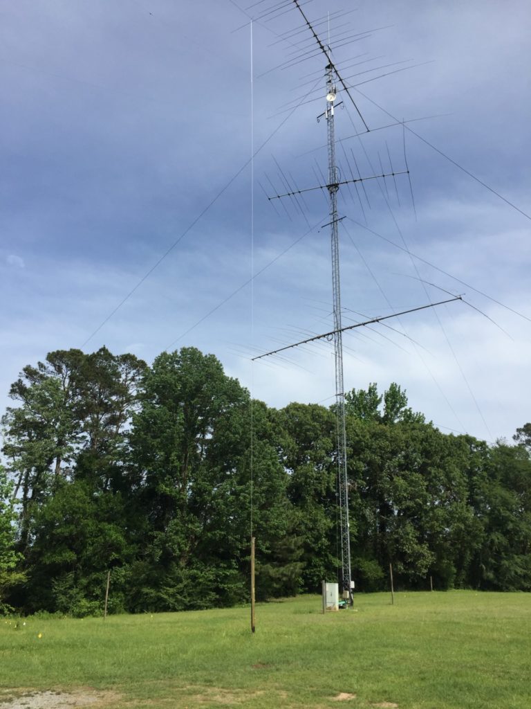
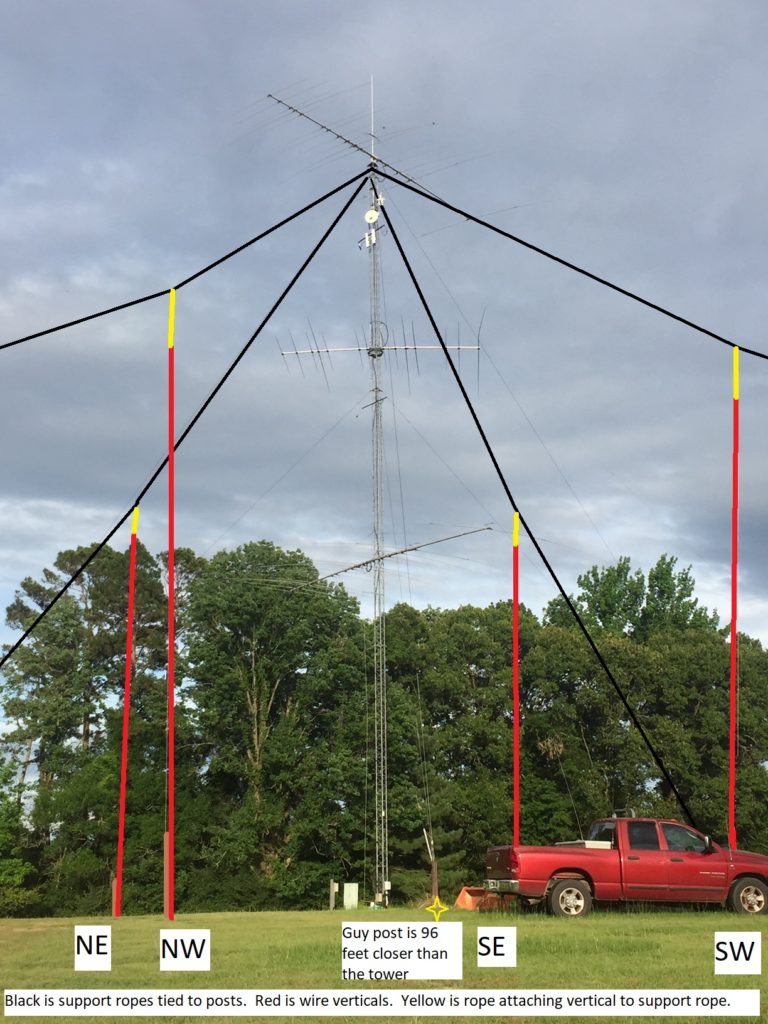
April 2020 – After several years of desiring to do so, my 80-meter 4-square is under construction! It will consist of 4 wire verticals, supported by ropes attached to the top of the tower and extending out to three 4 X 4 posts, with the final tie down on the roof of my shop. The vertical elements will be #14 stranded THHN wire, to homemade SO-239 feed point brackets.
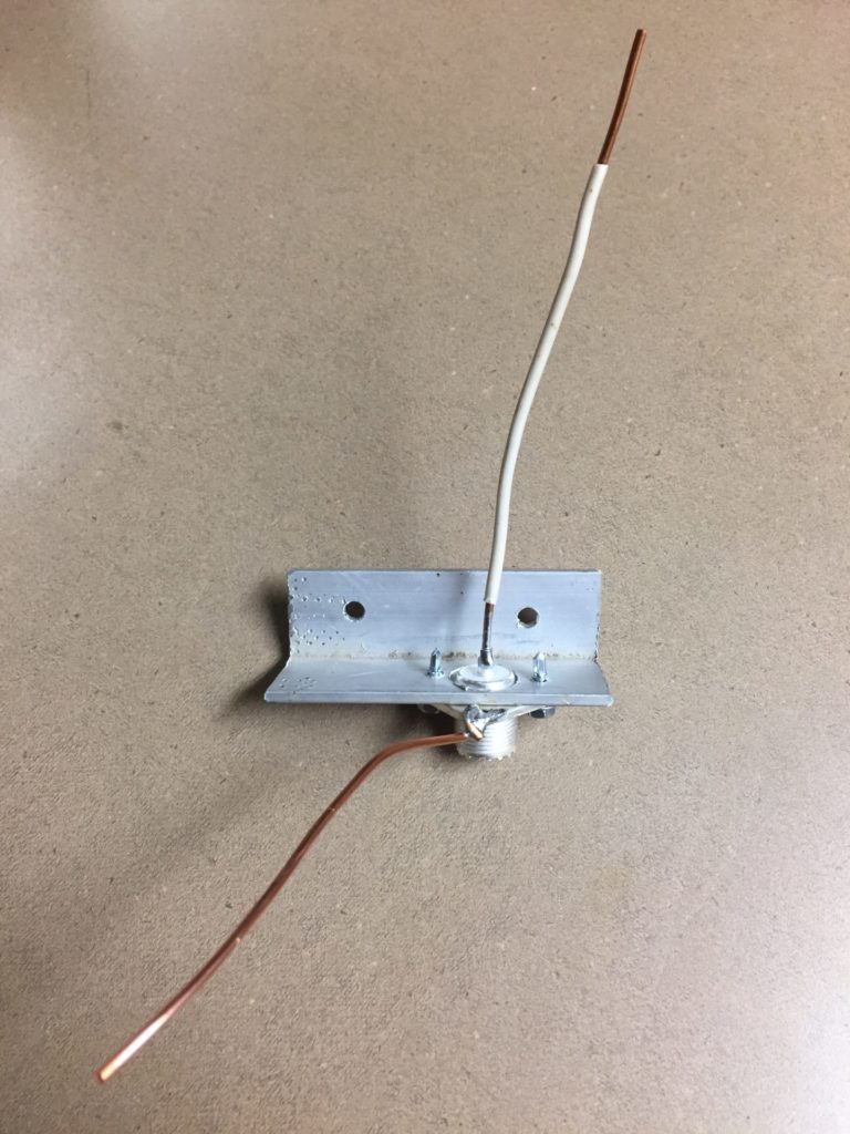
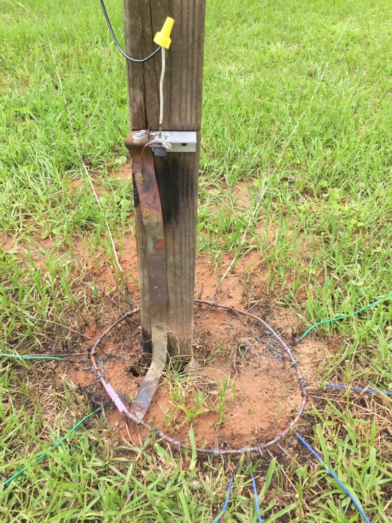
Home made feed point bracket to be screwed to 4 X 4 post. Ground wire soldered to body, which in turn will be silver-soldered to ground strap attached to ground ring.
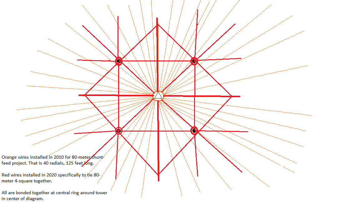
Each vertical wire and feed point are attached to a 10-foot 4 X 4 post. Each post has a #4 solid copper ground ring around it, initially with 8 radials. The central tower has 40 radials, each 125 feet long.
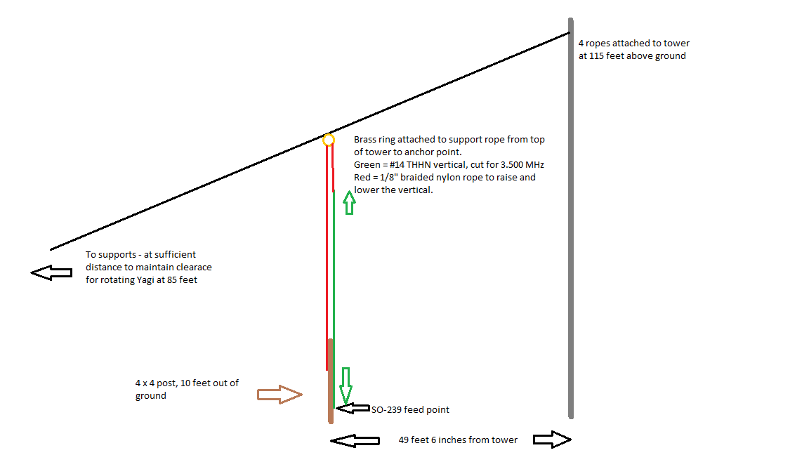
I am using a ComTek phasing/relay box and controller. The verticals are tuned for 3.500 MHz, and the 75-ohm 1/4-wave phasing lines are cut for 3.650 MHz.
5/9/2020 – With help from WM5H, KF5GDJ and KF5GDK, we installed the northwest vertical.
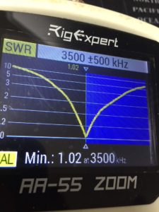
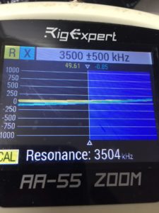
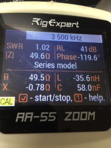
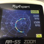
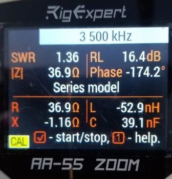
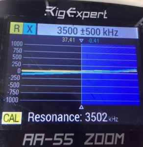
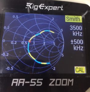
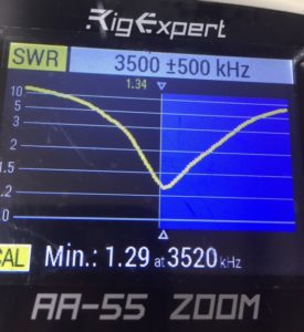
Using my AA-55 ZOOM, here are the electrical properties of the single vertical.
Greg continues, “One is that there is around 14 Ohms of ground loss, so 36 + 14 = 50 Ohms. The other reason is that some other structure is coupling with the antenna and that is “throwing off” the impedance. “
One way to check for ground loss is to add more “test radials”, and see if the resistance slowly drops as you add radials.
For whatever it’s worth, my assumptions about your ground are that the soil itself is more conductive and on the higher quality side for soil in the USA. [My soil is 6 mS/m. -W5WZ] I guess I think that because of the rich farmland assumption and no lack of moisture. You aren’t in Arizona or the granite state, New Hampshire.
Even though your verticals have “only” 8 radials located at the feed point, the addition of the tower ground system (IMHO) should create a decent RF ground.
Now let’s assume that there are 14 Ohms of ground loss. The implication is that the efficiency of the vertical is 36 / (36 + 14) = 72%, which is a signal strength loss of 1.43 dB. The 4-square should provide you with around 5.5 dB of gain, so, that would be reduced down to around 4 dB. Whether that’s a lot or a little is up to you.”
| Theoretical feed point impedance, A | Measured feed point impedance, B | Implied Ground Loss=B-A | Efficiency=A/B | Theoretical Gain, dB |
| 36 | 50 | 14 | 72% | 3.96 |
| 36 | 49 | 13 | 73% | 4.04 |
| 36 | 48 | 12 | 75% | 4.13 |
| 36 | 47 | 11 | 77% | 4.21 |
| 36 | 46 | 10 | 78% | 4.30 |
| 36 | 45 | 9 | 80% | 4.40 |
| 36 | 44 | 8 | 82% | 4.50 |
| 36 | 43 | 7 | 84% | 4.60 |
| 36 | 42 | 6 | 86% | 4.71 |
| 36 | 41 | 5 | 88% | 4.83 |
| 36 | 40 | 4 | 90% | 4.95 |
| 36 | 39 | 3 | 92% | 5.08 |
| 36 | 38 | 2 | 95% | 5.21 |
| 36 | 37 | 1 | 97% | 5.35 |
| 36 | 36 | 0 | 100% | 5.50 |
Greg continues, “If you do want to investigate the ground loss idea, then adding let’s say a set of 8 more temporary radials and then making a measurement, and then add let’s say 16 more (32 total) followed by another measurement.
If there is a coupling issue, then you figure the tower is a likely candidate for being the other resonant structure.”
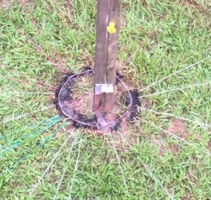
5/10/2020 – I added 6 more radials permanently – silver solder bonded all connections – using the remaining radial wire I had on hand. Two @ 65 feet long. Four to length to intersect “plus sign” ground bus.
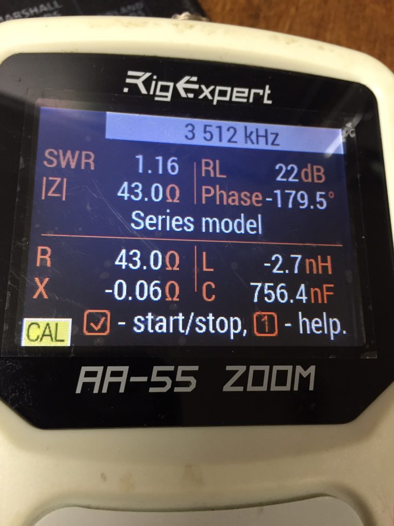
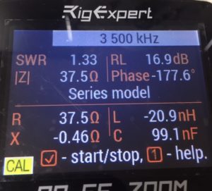
Feed point impedance now 43.6
Resonance moved from 3.504 to 3.511
SWR at resonance moved from 1.02 to 1.16
At this point, 36/43.6= 82.5% efficiency. 82.5 * 5.5 = 4.54 dB gain
If 6 radials moved from 72 to 84% efficiency, it will be worth it to go to at least 16 radials per vertical (this one now has 14).
5/13/2020 – Added 6 more radials (now have 20) and the R=39.3.
Emails exchanged between W5WZ and W3LPL on 5/14/2020
Hi Frank!
Building an 80-meter 4-square here. Given that:
*The vertical is an inherently unbalanced antenna.
*The 75-ohm 1/4 wave phasing coax is buried below grade to the vertical feed point.
*The shield is directly connected to the buried radial system, and
consequently earth ground.
Is a feed point common mode choke necessary?
–Scott, W5WZ
Hi Scott,
You’ve done everything necessary to suppress common mode,
nothing else is needed.
Common mode is a big problem with low sensitivity antennas
— especially small loops and Hi-Z verticals — and to lesser of a degree with Beverages.
73, Frank, W3LPL
5/16/2020 – I’ve added more radials (now have 23) and R=37.6. I’m completely out of wire, so have to buy some more. I will add radials until either R=36, or there are 32 radials.
5/16/20 – Feed point of NW vertical. Wire nut allows easy access to prune length of wire vertical. Once final tuning is complete, junction will be soldered.
5/18/2020 – Bought more wire. Added 7 more radials (total is now 30). I have concluded that I will stop adding radials to this NW vertical for the time being. Now I have to add 22 more radials to each of the remaining 3 verticals. I will buy 2,000 more feet of wire.
5/22/2020 – Now have 30 radials on the NW, SW, and SE verticals, with 15 on the NE vertical. Ran out of wire again. I will buy another 1,000 feet tomorrow. By the time this project is finished, there will be at least 4,500 feet of radials (held to the ground by at least 1,500 staples) installed specifically for the 4-square, all attached to the over 5,000 feet installed in 2010 for the shunt feed on the tower. That’s over 9,000 feet of radials.
RADIAL FIELD COMPLETED
5/23/2020 – With another 1,000 feet of wire, finished laying the radial field. All 4 verticals now have 30 radials. All joints are silver soldered.
With the AA-55 ZOOM on the NW vertical (the only vertical currently standing), the R has actually gone up. We did have significant rain earlier today, and the yard is squishy.
VERTICALS INSTALLED
5/24/2020 – With lots of help from WM5H, we got the remaining 3 vertical support ropes, and the verticals installed. Also completed the initial trimming and tuning of each vertical. Each now resonant in the range of 3.500 and 3.504. R range 36.9 to 38.0. We discovered that the tension/slack in the vertical wire elements seems to make significant changes to the resonant point. I’m talking only a couple of inches difference moves the resonance from 3.500 to 3.520 and back down to 3.490.
After working in the Louisiana heat and humidity for 6 hours, we are beat. Tomorrow morning I’ll remeasure each vertical and post the results.
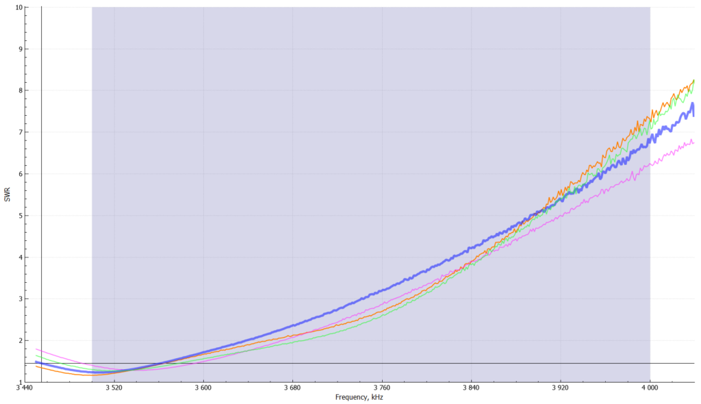
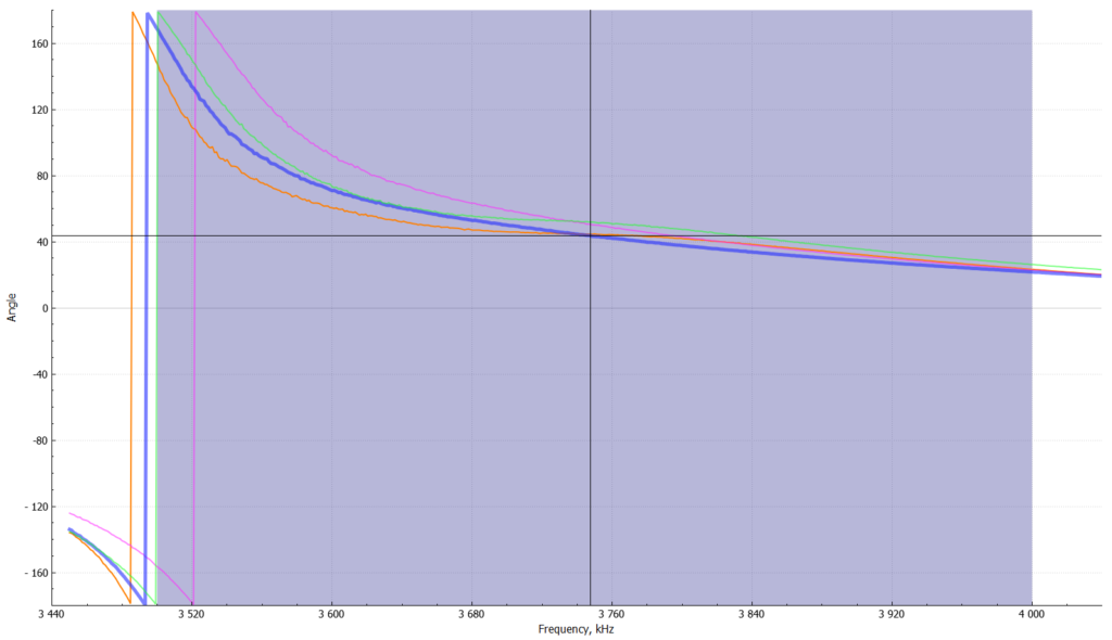
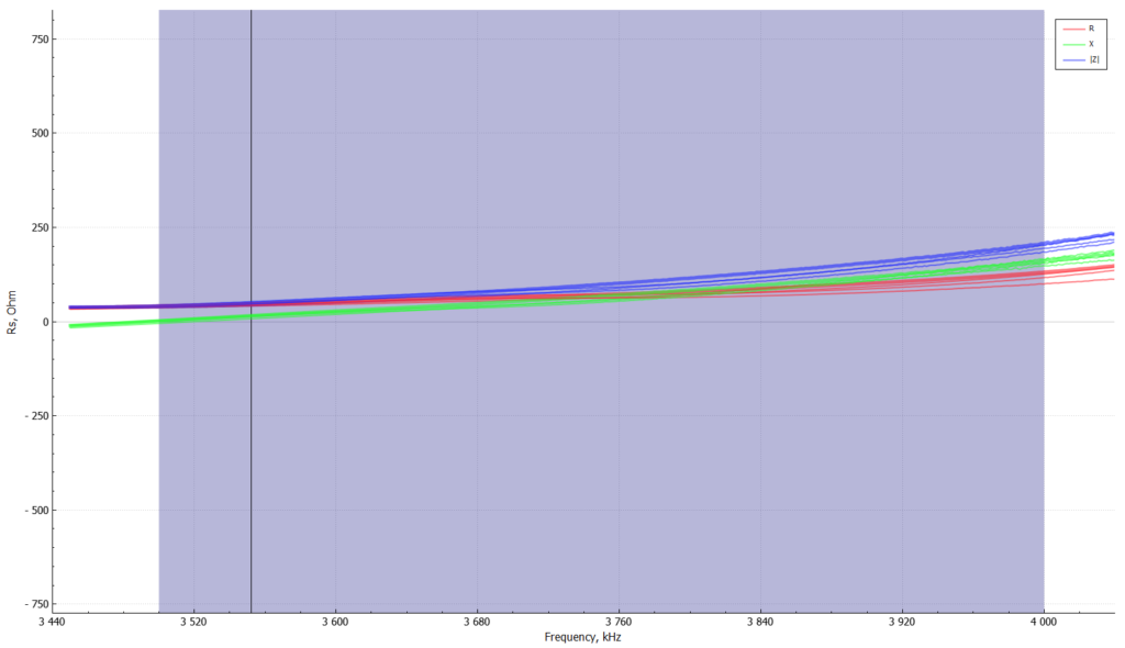
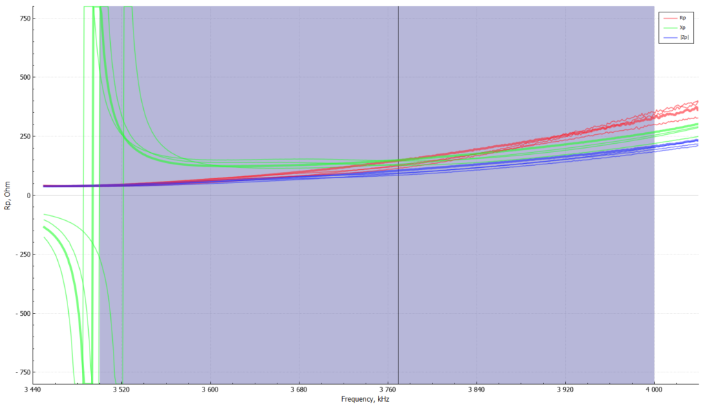
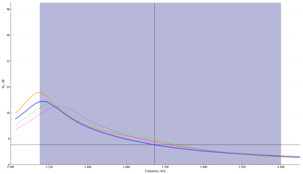
DETAILED SWEEPS
5/25/2020 – These sweeps were made with AA-55 ZOOM attached to my laptop using the AntScope2 software. The AA-55 was connected to the feed point of each vertical, with the other three floating.
| ComTek Controller (Orange jacket, 4-pair) | To Antenna Shed (Black jacket, 7-conductor) | To Telco Pedastal (Red jacket, 4-conductor, blue tape stripe) | To Phase Box (Black jacket, 7-conductor) | Phasing Box |
| 1 – Blue/BlueWhite | Yellow | Yellow | White | 1 – White |
| 2 – Orange/OrangeWhite | Brown | Black | Brown | 2 – Black |
| G – Green/GreenWhite | White | Green | Green | 3 – Green |
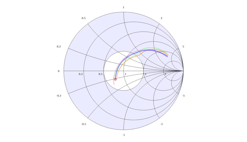
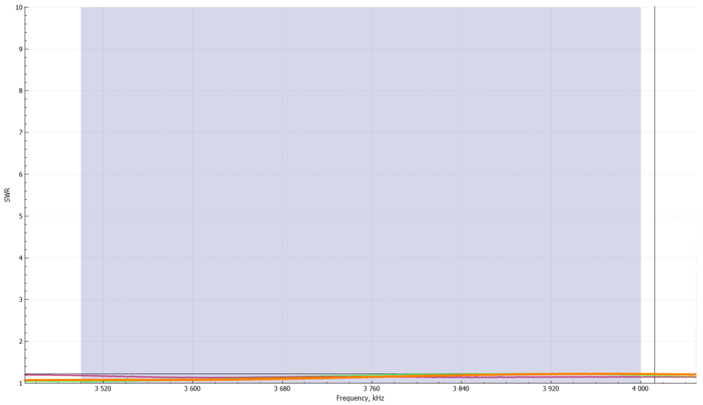
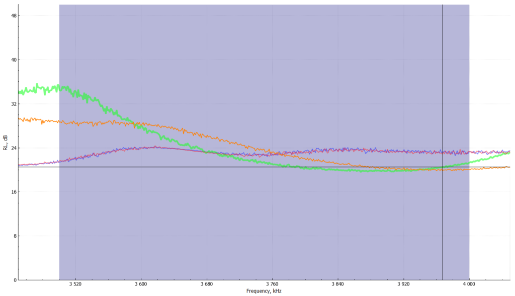
Detailed Sweeps of the Array
5/27/20 – These sweeps were made with AA-55 ZOOM attached to my laptop using the AntScope2 software. The AA-55 was connected to the input of the Comtek phasing box.
5/27/2020 – Called CQ to get some captures via the RBN. Interesting results, including some F/B calculations.
| Received | NE | NW | SE | SW | Column1 | FB NE/SW | FB NW/SE |
| AC0C-#: | 24 | 34 | 27 | 10 | |||
| CX6VM-#: | 18 | 17 | 1 | ||||
| DJ9IE-#: | 17 | ||||||
| DL3DTH-#: | 8 | ||||||
| G4HSO-#: | 14 | ||||||
| K1TTT-#: | 30 | ||||||
| K2DB-#: | 26 | 30 | 29 | 1 | |||
| K9IMM-#: | 31 | 19 | |||||
| K9TM-4-#: | 27 | 24 | 3 | ||||
| KC4YVA-#: | 27 | 26 | 26 | 18 | 9 | ||
| KM3T-#: | 30 | ||||||
| KM3T-1-#: | 28 | 10 | 18 | ||||
| KM3T-2-#: | 29 | ||||||
| KO7SS-#: | 12 | ||||||
| KO7SS-7-# | 18 | 20 | 22 | 31 | 13 | 2 | |
| N9YKE-#: | 19 | ||||||
| NC7J-#: | 20 | ||||||
| NN3RP-#: | 4 | ||||||
| OE9GHV-#: | 8 | ||||||
| VE3NZ-#: | 22 | 17 | |||||
| VE6WZ-#: | 17 | 8 | |||||
| W1NT-#: | 33 | 17 | 16 | ||||
| W1NT-2-#: | 13 | ||||||
| W3OA-#: | 43 | 34 | 39 | 5 | |||
| W3RGA-#: | 39 | 28 | 19 | 20 | |||
| W4AX-#: | 9 | ||||||
| W4KAZ-#: | 27 | 28 | 16 | 11 | |||
| W8WTS-#: | 22 | ||||||
| W8WWV-#: | 39 | 23 | 16 | ||||
| WA3OPY-#: | 15 | 6 | 11 | 18 | 3 | 5 | |
| WB6BEE-#: | 25 | 19 | 19 | ||||
| WE9V-#: | 32 | 23 | 21 | 11 | |||
| WZ7I-#: | 27 | 9 | 18 |
5/28/2020 – Had nice weather before sunset, so had a chance to have my son Delton KF5GDK in the shack to cycle thru frequencies and directions, with me at the phasing box to read the watt meter.
The Elecraft K3 was set to 100.0 watts, in FSK mode. Power out was verified by my LP-100A in the shack. At the phasing box, the dump power power was connected to a Daiwa NS-660A in the 30-watt scale. We communicated by radio, and each key down period was 2 seconds to allow the needle to settle. Granted, the markings on the Daiwa are not what you’d call precision, but I did my best to guess/approximate the graduations. Again, this is first run at it. Put it all in a spreadsheet and did the math to present it in dB form. dB = 10 log (P-dumped/P-transmitted) Added the measurements Greg gave me for a K3LR 80-m 4-square for reference sake.
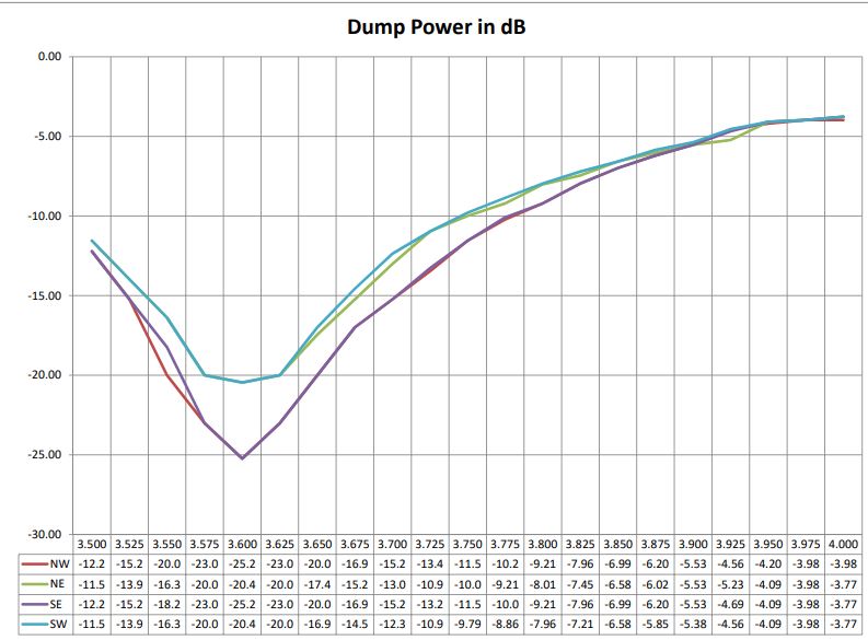
All in all, I think it looks good! Still some fine tuning left.
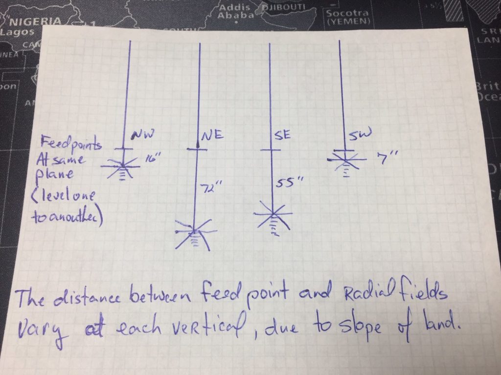
I did some dimensional measurements yesterday of the vertical distance between feed points and radial ring at base of post.
NW = 16 inches
NE = 72 inches
SE = 55 inches
SW = 7 inches
Also measured the sides and diagonals of the square to the center pin of the feed points.
Sides E-W is 6 inches wider than N-S. Explained by my posts being set on the wrong side of the stake when I originally laid out the square.
Diagonal NW-SE is 1 inch longer than NE-SW
Thanks to K8AZ, W8WWV, K8NZ, W3LPL, W3YQ, WM5H, K5RUS, KF5GDJ, KF5GDK and KF5MTH for the help along the way. I’ve learned a lot, and can already see this project was worth the effort!