SUMMARY – KIO3 ACC pin 9 voltage not stable when tranmitter is placed in TX. Sypmtom exhibits on 30m, 20m, 17m and 15m.
DETAILS – K3 KIO3 connects only pins 3, 9, 13, 14 to a Top Ten Band Decoder, and has been for many years. Now when K3 is on 30m, 20m, 17m, and 15m, any mode, at any power level including 0.0 and TX TEST, upon going into TX the voltage on pin 9 drops to 2.3-2.5vDC, thus improperly signaling the band decoder to switch bands, when indeed the K3 has not changed bands.
7/25/2023 – Email from Elecraft Support:
A note from our senior technician : “Since it has been working for years, I would check all the chokes on the KIO3 Digital board. (Ohmmeter read across the bus lines should be about 4 Ohms. if open, they can be jumpered) Pull and reseat the KIO3 board set also, I believe we went to gold pins on the K3″S”.
While reseating KIO3 boards photograph both sides of the digital board and send the photos back to this address.
That rig # came with NO pullup resistors, so I wonder what version digital board it has (version XD), send pic of the Digital board please. Then look at the schematic for HIS board. Not sure where the ~2.5 volts comes from (Pin 5 of U6).
8/7/2023 – Received a new Rev C board that does include the pullup resistors. Installed the board, and everything works as it should.
1/16/2023 – As the station grows and matures, there is always work to be done!
This evening I accomplished some improvement items in the shack for position C, to enable more efficient in-band Search & Pounce integration with position B
Installed Y-Box on K3 at position C
Built cable to connect EA4TX Interlock to Y-Box at position C
Built cable to connect Top Ten Band Decoder to Y-Box at position C
Built cable to connect Top Ten Band Decoder to Dunestar 600 bandpass filter at position C
Tested the function of Y-Box, Interlock, Band Decoder, and Dunestar at position C
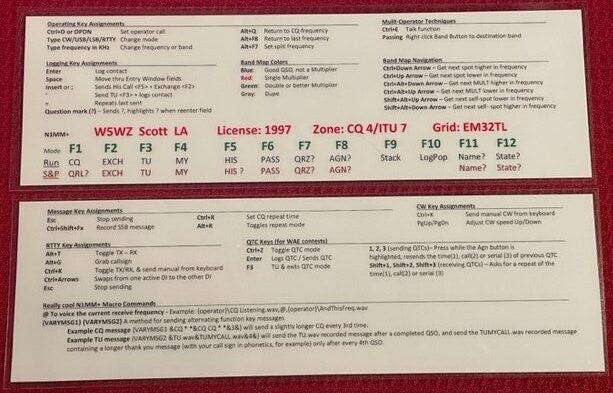
1/18/2023 – I made six laminated N1MM+ “help” cards, containing many key assignments and some cool macro commands. They are printed on both sides, with unique data on each side. The MS-Word file is available here.
Laminated N1MM+ “hint card”. These should be an asset to operators in the fog of war moments.
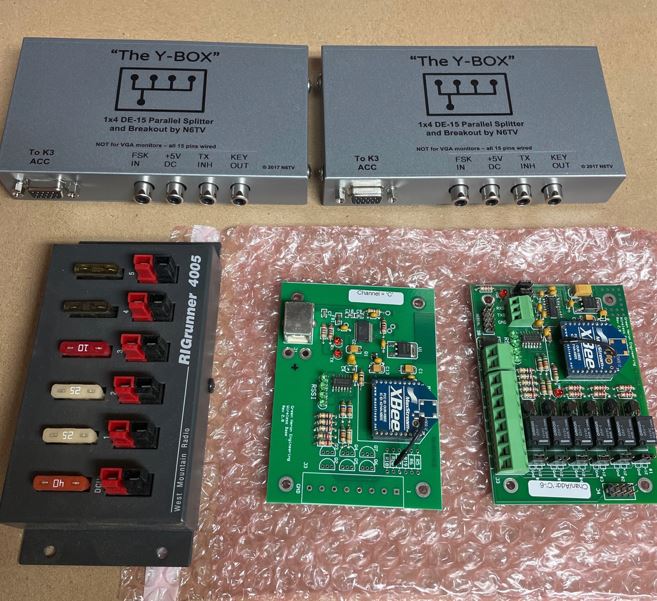
Most hams acquire stuff over time for their use and enjoyment. I’m no different. Here are some recent acquisitions.
Y-Boxes for use with K3 and accessories, RigRunner, Green Heron Zigbee boardsSingle band pass filters
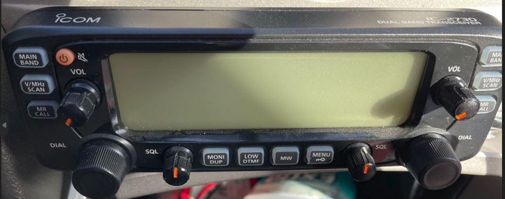
And recently, I acquired a used IC-2740 for my car. It has been over 9 years since I had a radio in my car. As I commute 100 miles each day for work, having a radio again has been nice, even though repeater activity is not very high. The knobs on the IC-2740 have a depression on them to indicate position of the knob, but black on black was not very helpful. Using a toothpick and some orange acrylic paint, that problem is solved.
1/10/2022 – The TicRing at 85 feet recently quit turning properly. I finally found time to document my findings and pose the question to CQ-Contest.
Physically, the antenna appears to be pointed about 150 degrees. The controller displays 60 degrees. Turn knob CCW to any position beyond 30 degrees and push start, nothing happens. However, with the knob at about 35 degrees and any where CW to 180, a brief tap of START elicites a sharp BUZZ (like an alarm sounder) from the controller. It also appears to rotate the antenna CW; I quickly turn the know CCW to stop rotation, because I don’t want to over-rotate and put coax in a bind.
I don’t see anything in my TicRing manual about an alarm buzzer, nor do I see any resistances for troubleshooting from the ground. I suspect others have encountered this before, and am hoping to get some hints before retrieving the motor from the tower.
I received helpful replies from N4TZ and K3LR
The buzzing you hear from the TIC controller is the relay chattering. That is caused, I think, by holding down the start button (telling the motor to go) while the controller is trying to get the motor to stop turning because it senses that the motor should not run.
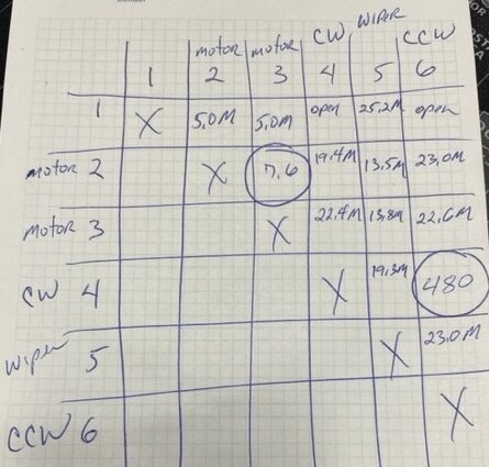
There are five wires to the rotor – two for the motor, three for the direction indicating potentiometer. The motor windings are low resistance, under ten ohms (plus your wire resistance). The direction indication is 500 ohms from the CW to the CCW terminals, with the wiper in between. If the controller does not sense the wiper between the CW and CCW, then it will stop!
It has been known that the pot shaft is sideloaded by the gears such that the wiper will temporarily lose contact. A “fix” is to put some resistance across the controller terminals to make the controller think the rotor is within the range it wants to be and thus the motor will start, moving the pot past the bad spot. In my experience, when the controller had such problems, the needle on the meter would bang to the physical limit, and putting some external resistors would make the meter move back on scale.
The problem with the chattering was, I recall, from the center wiper connection losing contact with the winding. The resistance between the wiper and CW should be minimal when the rotor is turned fully CW (150-180 degrees).
Terry N4TZ
Your report sounds like a POT problem (defective). It is 10 turns and 500 ohms and available at DXE. I suggest you replace the POT and calibrate to zero degrees. With a new pot at the controller you should see 500 ohms across the pot. Zero degrees is when the wiper is at 250 ohms. The ends are 50 and 450 ohms. Only 400 ohms is used to go 360 degrees. You could also have a problem with the gears that drive the pot – make sure you check them.
Tim K3LR
Resistance measurments at the shack end of the control wires, disconnected from the controller. Note 4-5 is esentially open.
With the advice from N4TZ and K3LR, I’ve ordered a replacement POT from DXE.
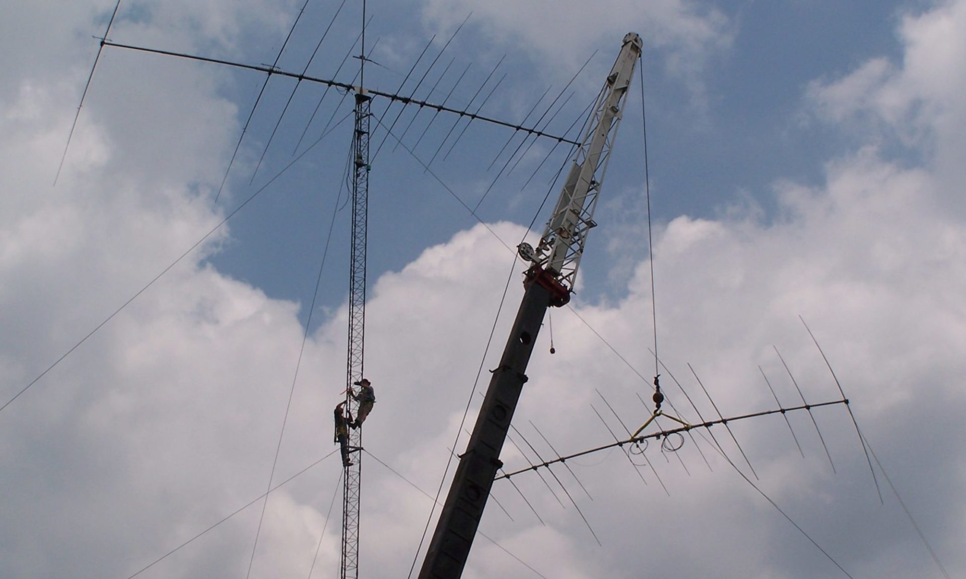
1/14/2023 – The package from DXE arrived last evening. This morning in the sub-40 degree temperature, with heavy frost on the entire tower, I climbed up to retrieve the TicRing motor. Before descending, I manually rotated the C-31XR to about 30 degrees, where it would be fine to sit for the NAQP CW contest that started in a few hours, just in case I didn’t get the repair completed and climb back up to reinstall the motor.
On the workbench, disassembly was made easy via the anti-seize compound applied to all the bolts the last time the position pot was replaced. My Weller soldering station makes this work quick and easy – desolder the three wires, remove the pot, install the new pot, ensuring it is set at the center of its 10-turn range, reattach the wires via soldering, and test the motor. Tested perfectly. Back up the tower to reinstall the motor and have the ground crew visually calibrate the antenna, then back to the ground and in the shack to verify calibration.
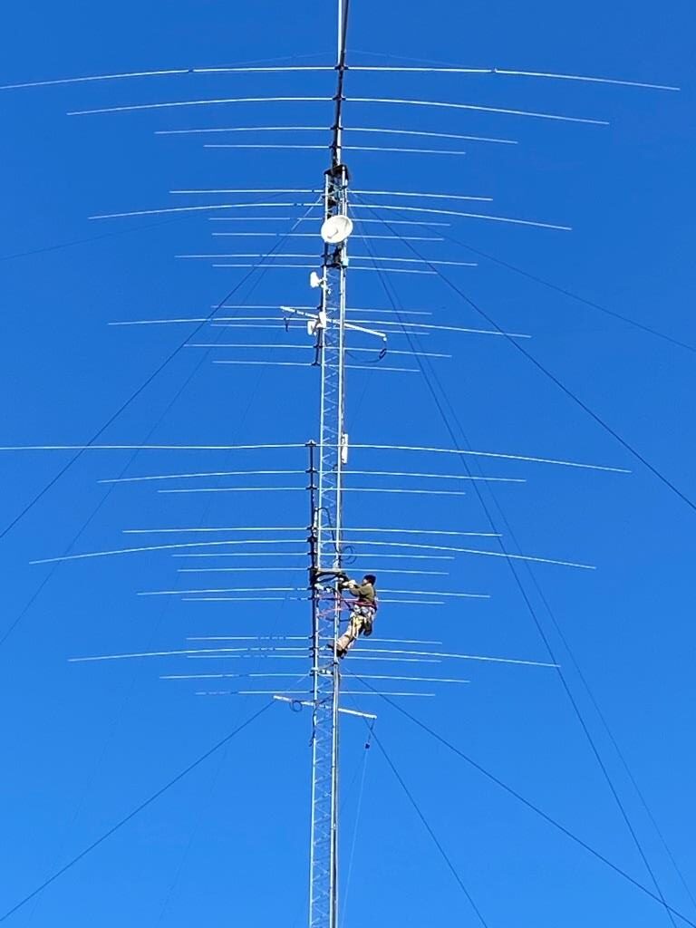
W5WZ reinstalls the TicRing motor after replacing the potentiometer. This Force 12 C-31XR is at 85 feet above ground. Photo by K5TS
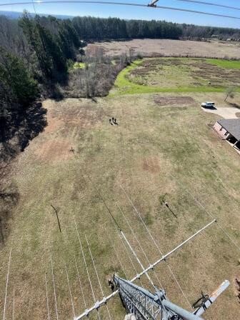
Ground crew assists by visually sighting the middle antenna with the upper antenna pointed due north.
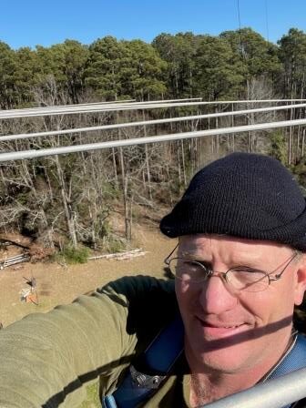
W5WZ was the climber for the repair in this obligatory selfie at 85 feet above ground.
I sent K5TS, W5LA and KD5YS outside with a walkie-talkie to be my eyes while I handled the control box calibration duties. Got it all finished 45 minutes before the start of NAQP CW.
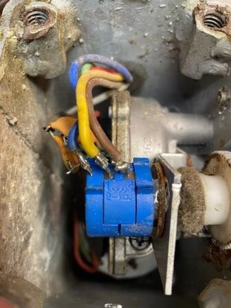
The bad pot to be replaced. The newly installed pot is the third pot that has been in service since the TicRing was installed.
Hints I’ve learned:
==> Grind a small flat area on the pot shaft so the set screw in the plastic gear will actually prevent the gear from slipping on the shaft
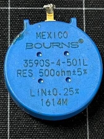
The base of the bad pot. Bourns 3590S-4-501L RES 500ohm+/-5%. Mouser #652-3590S-4-501L
I have been trying to setup up the K3 and Mumble to enable proper audio for remote operation. The issue encountered was at the remote location, microphone input was being played back into my ears with the round trip induced latency, essentially “jamming” my ability to speak coherently.
Thanks to an email with the exact solution from Kazu M0CFW, M5Z, JK3GAD, I have figured it out! K3 LIN OUT has a TX MON setting that was added later than my printed user manuals (K3 # 251, so it has been around a while).
K3 MCU 5.58 / DSP 2.88 / FPF 1.26, 3-16-2017
* PREAMP 2 (ON KXV3B) NOW USABLE ON 15 AND 17 M: PREAMP 2 improves noise figure by about 6 dB on 15 m and 3 dB on 17 m relative to PREAMP 1.
* TX LINE OUT (MONITOR) LEVEL NOW ADJUSTABLE: In CONFIG:LIN OUT menu entry, tap ‘2’ (REV switch) to set the “T=” level (TX monitor). Tap ‘2’ again to return to the RX LINE OUT setting
K3 documentation and software update
All three of my K3 had TX MON = 30. Adjust to 0, Mumble problem 100% resolved!
I remember now that this was set to provide ability to record N1MM voice keyer messages on the fly! Because I didn’t remember, I’ve made notes in the config matrix of all my K3 manuals.
1/2/2022 – With the upcoming Bouvet DXpedition, now seemed like a good time to improve my beverage receive antenna for the SE direction. The current SE beverage was 480 feet long, and is run on the same posts, 2 feet above the primary NW beverage.
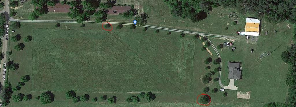
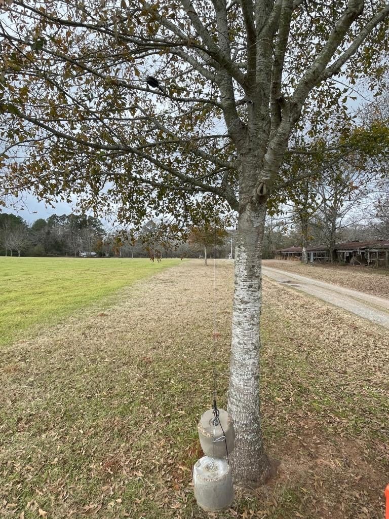
Several years ago, I planted some oak trees on the north and south sides of my property, which is primarily a pasture. They have grown, and now are adequate to anchor the ends of beverage receive antenna wires. I selected an appropriate pair with a 310/130 heading between them. These trees are 525 feet apart, for an additional 45 feet of length for this antenna.
Selected trees for this project circled in red
In the past, I had watched a YouTube video by Steve VE6WZ and his beverage installation techniques. Borrowing heavily from his method, I commenced my work.
At 12 feet above ground level, I drilled a 5/16″ pilot hole to install a 3/8″ hot-dip galvanized eye bolt. At the fixed end, a 3-foot loop of rope and an insulator are attached to the eye bolt.
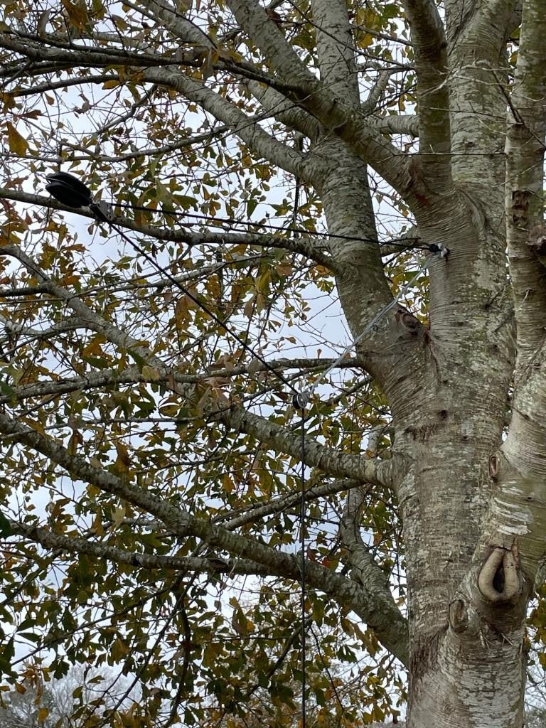
For the floating end, I began exactly as VE6WZ demonstrates in his video. However, with 80 pounds of counterweight via the single pulley method demonstrated by VE6WZ, the wire was still sagging more than I desired. At this point, I decided to implement a 2:1 pulley block method to multiply the tension to 160 pounds.
Overview of the 2:1 pulley block tension method on my SE beverage. 80 pounds of actual weight has tensioned this 525-foot wire keeping it about 12 feet above ground across the single span
17-gauge galvanized steel electric fence wire has a breaking strength, depending on which source for specifications you trust, between 125 and 176 pounds. Thinking that I may be pushing my luck with 160 pounds of tension, I removed 40 pounds of weight, lowering the tension to 80 pounds via the 2:1 pulley block. The entire span is still sufficiently high above the ground. With storms approaching, that’s the end of work for today.
Closeup of the pulley block arrangement to achieve a 2:1 mecahnical advantage
Additional plans:
3 ground rods (1/2″ copper pipe, 3-4 feet long) at both feed point and termination ends
Soldered, rather than compression ground wire connections to ground rods
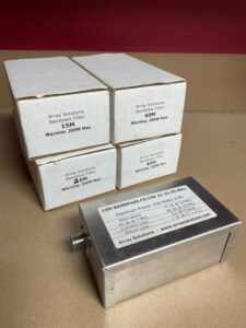
12/17/2022 – the weather was forecast to be cool, but sunny. WM5H and I drove over to Minden, Louisiana to the MARA Annual Christmas Hamfest. We got to see some friends and swap some good stories.
WM5H and W5WZ at MARA hamfest
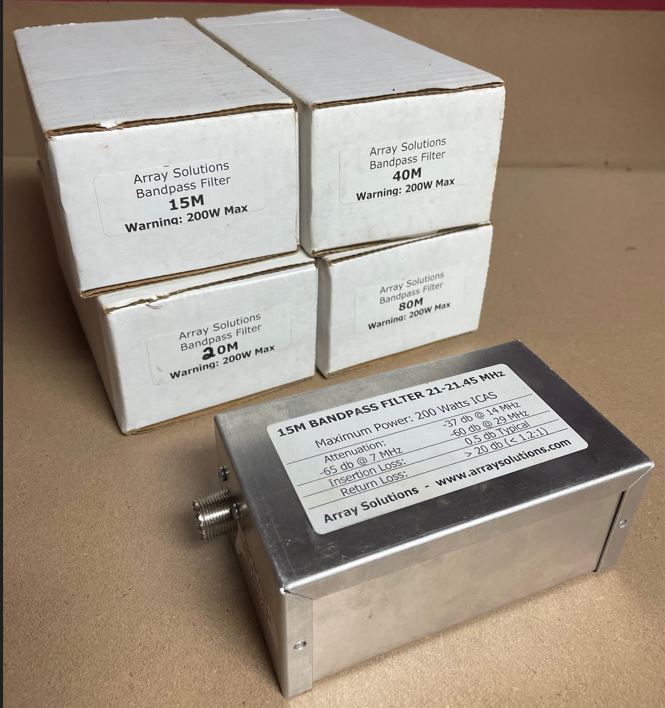
In the swap tables area, I bought a set of Array Solutions band pass filters for a fair price.
On Sunday 6/12/22, I was checking out the station ahead of our club’s upcoming Field Day. Running through the stacks on Tower #1, I encountered troubling readings on the 20 meter stack.
SWR on each of the three measured independently was fine; however any combination of 2 or 3 antennas sent the SWR to >6:1.
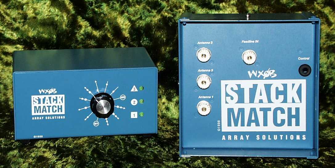
On Tuesday 6/14, I went to the cabinet at the base of the tower. I disconnected the feed lines to the three antenna from the Array Solutions Stack Match. Measuring each antenna with my Rig Expert AA-55 Zoom, I discovered that everything up the tower checked out in 100% working order.
Since I had several new Stack Match relay boxes on the shelf, I simply replaced the relay box.
Of late, I’d noticed that the SWR on the 10 and 15-meter stacks on tower 1 seemed to be getting higher and higher. Sometimes our first reaction is to head up the tower to the antenna to find out what is the trouble. This time, however, I didn’t go with that first gut reaction.
Rather, I began with a very methodical testing routine, with my AA-55 ZOOM connected to the coax in place of the transmitter at position A. I then inserted a precision dummy load at the next coax junction. Next, using the AA-55 I swept the coax on all 6 ham contest bands. I followed this pattern until I found SWR readings higher than 1.2:1.
The first thing I found was my ICE 419B bandpass filter. Even in bypass mode, it drove the SWR higher than 1.2:1. I inserted a brand-new barrel connector in its place, and continued my testing.
The next problem found was on the output side of my 10-m coax filter stubs. I replaced the stub assembly with another barrel connector and continued the testing. Likewise, I found the 15-m coax filter stub assembly and the 40-m assembly to be causing SWR problems. More barrel connectors and the testing continued until I reached the distal ends of the six runs of hardline at the inputs of the various Stack Matches at the base of the tower.
The first step at remediation and repair was to test each individual coax stub in the 10, 15, and 40-meter assemblies. I found all of them to be considerably low in frequency relative to what I desired them to do. So, using the AA-54, I retrimmed each of them to return them to the proper frequency. Then I reassembled everything and retested. SWR was flat all the way to the base of the tower.
The second step was to replace the ICE 419B at position A and position B with Dunestar Model 600 filters. Following that, I again retested all the way to the tower. SWR was flat!
Things that make you go “Hmmmm”. My stubs reside in a shed, out of the sunlight and out of liquid rain. What caused them to drift over time and appear too long electrically?
The ICE419 series automatic bandpass filters are known to have low reliability. This and my experience with them over the years have led to their retirement in transmitting RF paths at W5WZ.
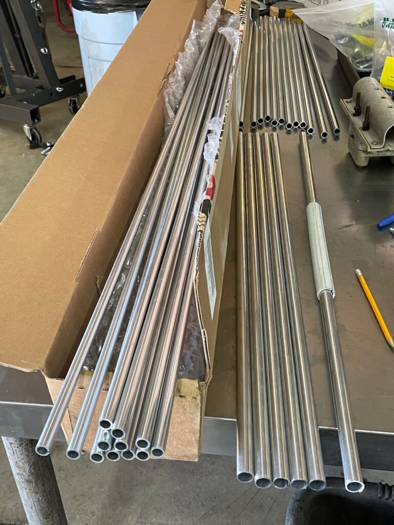
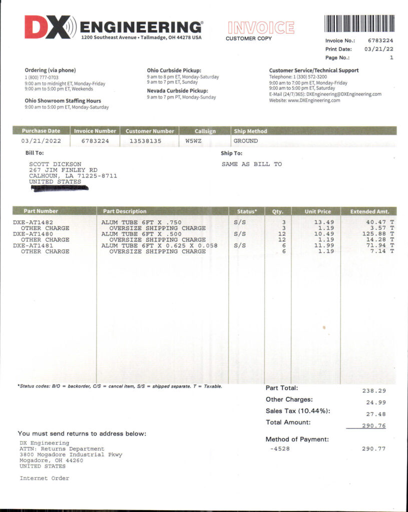
3/27/2022 – With a box of shiny tubing from DXE, and an OWA design from my friend, I tackled an antenna construction project today.
Shiny tubing for tower bling!
Since selling my Lightning Bolt 2-element 5-band cubical quad a few years ago, I have not had an antenna for 12 meters. My DXCC count is low on that band, so I figured that with the uptick in propagation, now is as good a time as any to tackle this project.
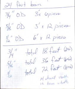
Some time ago I asked around for an OWA design to use a 24-foot boom (salvaged from an old TH6?). Once I had the design in hand, I plugged it into EZNEC 6.0, and agreed with the designer’s conclusions. Download my EZNEC file for this antenna. I made a parts list and placed an order from DXE for the tubing (surely there are others suppliers around, but I can’t find them using Google search) and another from McMaster-Carr for the hardware needed.
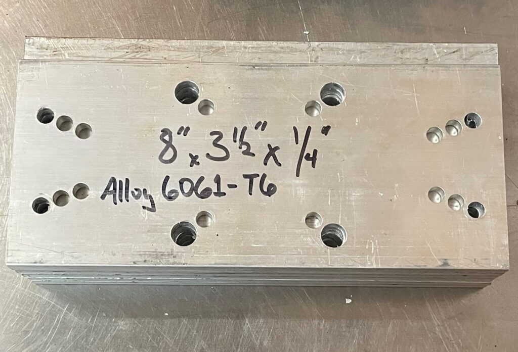
With some aluminum flat bar cut to length, a drill press made quick work punching holes in the boom-to-element plates (I used a DXE model as a template).
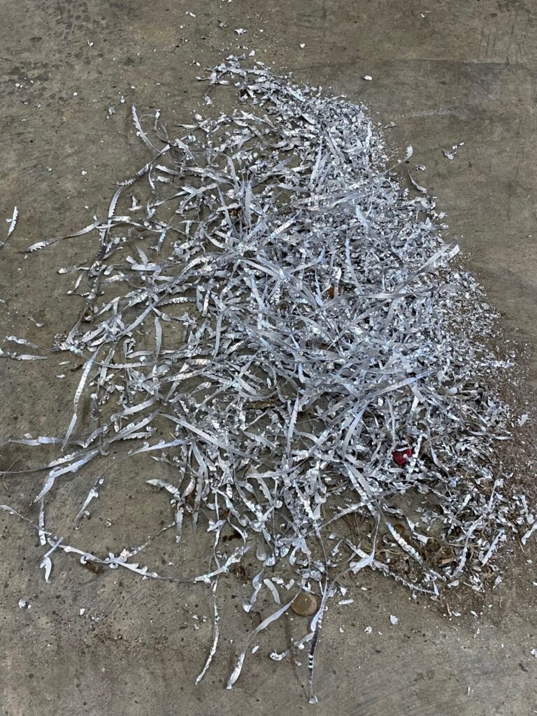
A pile of shavings!
Stack of six boom-to-element plates
The Sawzall was employed to cut the tubing to the needed lengths, followed by a thorough deburring of all tubing ends. Measured and marked the “exposed” lengths of tubing, inserted to the marks, and drilled three 1/8″ holes for pop rivets. Pulled the tubing out, deburred the drilled holes, then coated the insertable tip with a copper-impregnated anti-seize compound. Aligned the holes and riveted the tubing together. The halves of the driven element are separated by 2-inches, supported by a 0.75″ fiberglass rod inserted into both halves.
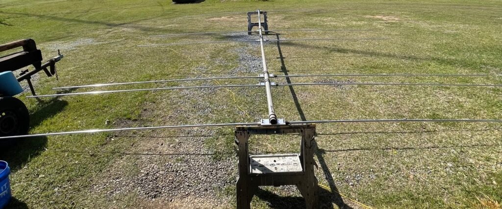
With the elements assembled, I moved outdoors to assemble the boom and install the boom-to-element plates. After that, installing the elements was a piece of cake.
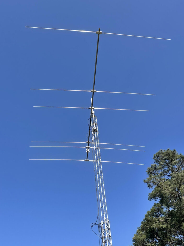
This perspective doesn’t present the antenna well
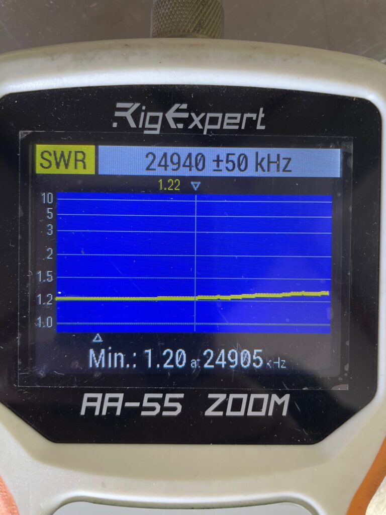
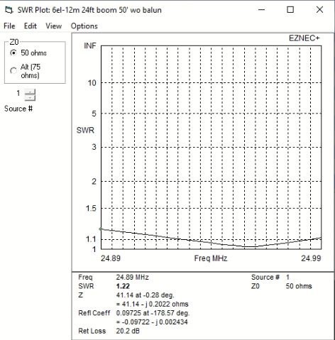
Still sitting on sawhorses, the initial SWR and R,X sweeps are nearly identical to the EZNEC model, and this is direct-feed.
Initial sweep still sitting on sawhorsesEZNEC 6.0 model’s SWR curve
I’ll update this post when the antenna is in service. I think it is going to be a flamethrower!
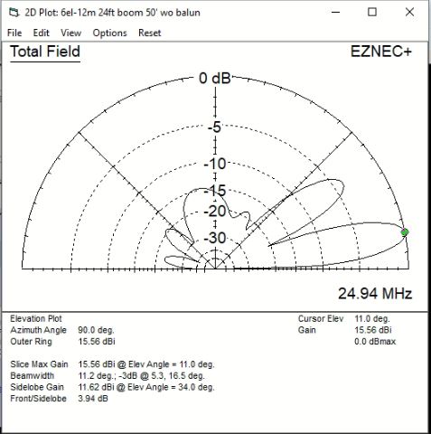
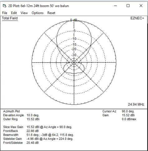
EZNEC 6.0 modeled pattern
4/15/2022 – Good Friday, and good Friday! I was off work. Woke up at 0400 and was wide-awake. Decided today was a good day to install the antenna. So, working alone with tractor and pallet forks, along with an 8-foot ladder, I was able to remove the KT-34 and install the 12-meter yagi. Initial tests are promising – worked YV4 and VP2V right away, 100 watts CW.
4/15/22 – 12-meter yagi now flying at 50 feet
A comparable commercially build yagi is the M2 12M4DX which is priced at $1,908.95.
The parts list
I used a Balun Designs Model 1115t – 1:1 Isolation – Suppression Balun at the feed point, cost to my door about $65.
Aluminum isn’t cheap, but this beats buying a commercially built antenna