WARNING – LETHAL VOLTAGES!!! DO NOT ATTEMPT WITHOUT PROPER SAFETY PRECAUTIONS!!! I’m not responsible for what you do with this information!
The Ameritron AL-1200 has a 3,600v power supply. Its filter capacitor bank of eight, 270mF 450vDC runs right at the limit of its design (8 x 450 = 3600). A common modification is to add two additional capacitors, along with the needed bleeder resistors, to increase the filter bank capacity to 4,500v. Keep in mind that the transformer still puts out 3,600v, so this modification essentially allows the components in the filter bank to have some overhead capacity.
W8JI and W7RY both offer a replacement PCB designed for 10 capacitors. W1QJ described the way he modified an AL-1200 for W2RE. I choose to adopt the W1QJ method, and will show how I did it here.
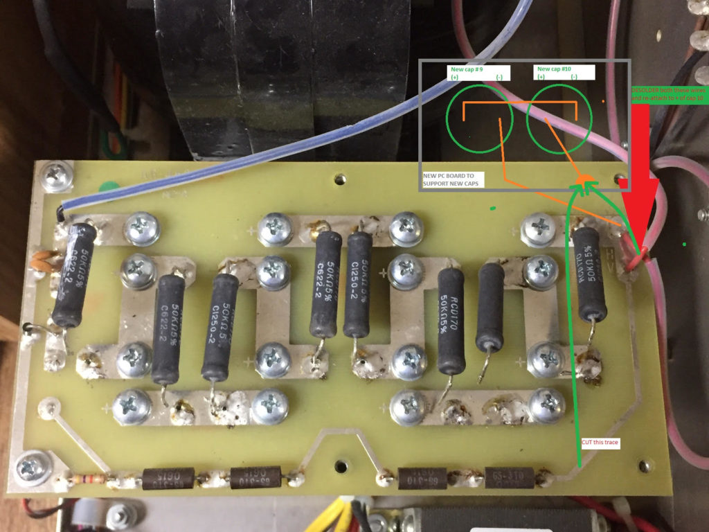
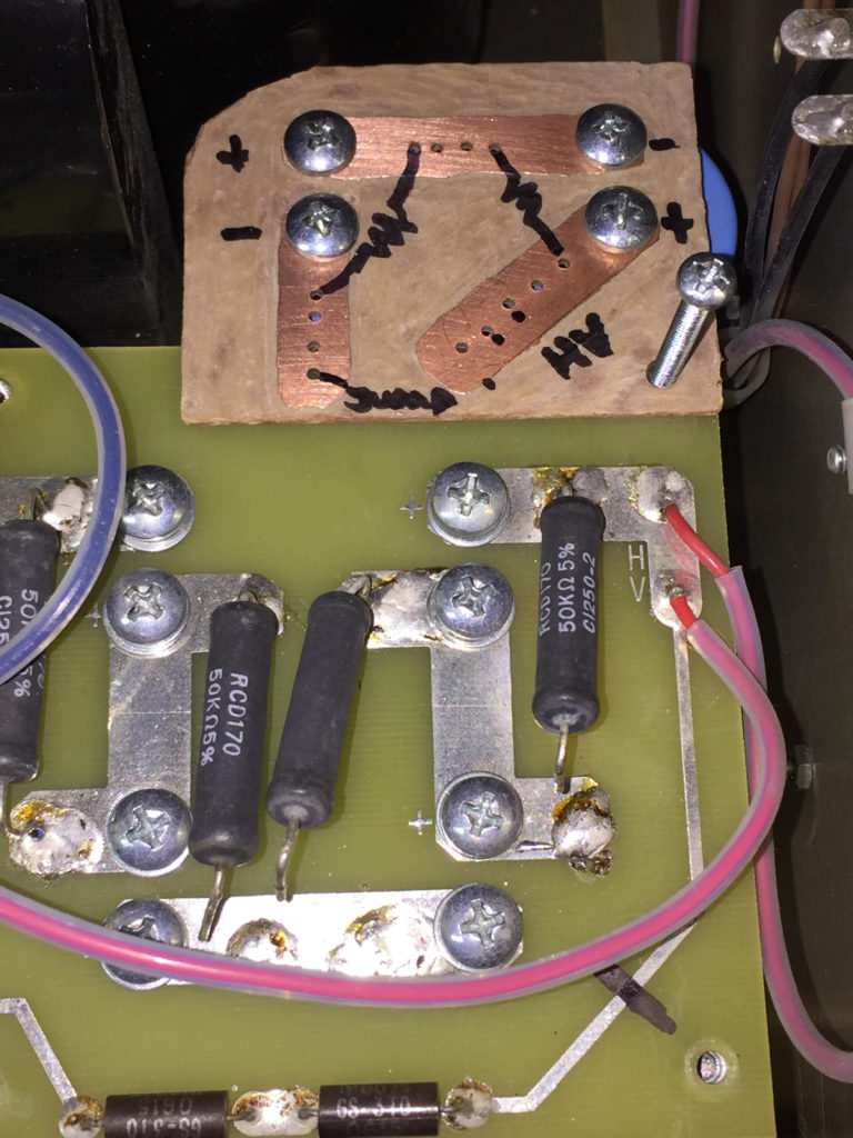
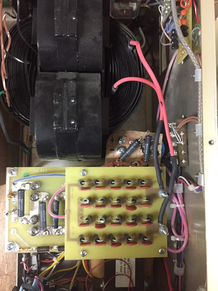
The modification involves adding two capacitors in series with the existing capacitor chain, with a bleeder resistor across the terminals of each capacitor. I’ve done this by constructing a small PCB that I’ve added to the amplifier. Then, move two HV wires, cut a HV trace and add a jumper for the metering, and add a jumper to complete the HV series circuit.
Hello Scott from Finland! I have had the Ametritron AL-1200 linear amplifier for a few weeks and it works well. I’m mostly at 160m and I get out of it at about 1300W. I would be interested in adding two electrolytic capacitors to the power supply section. I understand that it raises the voltage to 4000 V, but does that voltage decrease when the linear load is applied? Is there well room for two additional capacitors? This would be an interesting experiment and I have a Harris RF302 tuner that can withstand higher power. Would you recommend me to make this change? I think I could take the maximum power with a lower anode current. Maybe the tube Eimac 3CX1200A7 will get longer life then? I would be grateful for an answer. 73’s Esko / OH3EM
Hello Esko!
I made the modification to add the two additional capacitors to give more headroom, as the original design with eight 450 vDC capacitors was right at the 3,600 v output of the Peter Dahl HV transformer. I had struggled with weak or failed filter capacitors bleeder resistors; the first symptom of this was usually sagging HV when going key-down. In those instances, the key-down HV would drop to ~3,150 volts on the panel meter. After the +2 capacitor mod, key-down voltage is rock steady at ~3,600 v.
All the best,
Scott W5WZ
Thanks Scott for the reply. I also have a key down voltage drop of about 300 volts. Does it also affect the output power somewhat, I think so. I don’t dare make the change myself, but maybe sometimes I get it done. Best regards de Esko OH3EM.
Esko,
Yes, key-down HV drop will affect output RF power.
–Scott
What kind of power change should you see if you do this mod? Sometimes my voltage sags at home during extra hot and extra cold weather. I know this tube is pushed to 4500V in some other applications like the Henry amp.
Hi Jim,
The modification doesn’t really add any output power, as the transformer’s secondary output voltage has not changed. What it does do, however, is prevent output RF power from sagging when key down, and provides more overhead for the capacitors and bleed resistors. The original design of eight 450vDC capacitors is good for 3,600 volts, which is right at the HV AC output of the factory transformer. Adding the extra two capacitors takes this limit to 4,500 volts, thus giving component overhead and preventing RF power sag at key down.
–73,
–Scott, W5WZ
I now have 10 caps in my AL82 but still realize some sag at key down. The resting voltage however went from 3400 volts to 3600 after going to 10 capacitors. As for the 3CX1200D7 tube, Eimac shows absolute ratings as 5.5kv at 800ma. That tube will really get going at 4kv and up.
Bill – K1XT
Bill,
Thanks for the feedback. Did my page inspire you to add capacitors to your AL-82?
Yes, the 3CX1200 likes HV, just as the 8877/3CX1500 does.
73,
Scott, W5WZ
Thanks Scott. I managed to get 6 pieces 500 VDC and 2 pieces 450 VDC electrolytic capacitors. The common voltage at these is 3900 VDC. They are screw-mounted like the originals. I haven’t installed them yet. What do you think is this ok when the two pieces are at different voltages. They are connected in series. Best regards Esko OH3EM
Esko,
If it were me, I’d want all the capacitors to be the same value, as well as all the bleeder resistors to be the same value.
The guts of this amplifier have very high voltages, and margin for error and safety is important!
–Scott
So how much power does this actually add. Am considering doing the mod?
Hi Bob. The modification doesn’t really add any output power, as the transformer’s voltage has not changed. What it does do, however, is prevent output power from sagging when key down, and provides more overhead for the capacitors and bleed resistors. The original design of eight 450vDC capacitors is good for 3,600 volts, which is right at the output of the factory transformer. Adding the extra two capacitors takes this limit to 4,500 volts.
–73,
–Scott, W5WZ
So no extra output? Figured that were the whole purpose?
Nope. Just stabilizes and keeps components from operating threshold of their design limits.
Yes, Scott. The eight caps in my AL82 really did run it to the ragged edge. Depending on the incoming 240vac, there were times when the 82 showed 3700. A bit too much for comfort. Ten caps really is the way to go.
Bill – K1XT