WARNING – LETHAL VOLTAGES!!! DO NOT ATTEMPT WITHOUT PROPER SAFETY PRECAUTIONS!!! I’m not responsible for what you do with this information!
The Ameritron AL-1200 has a 3,600v power supply. Its filter capacitor bank of eight, 270mF 450vDC runs right at the limit of its design (8 x 450 = 3600). A common modification is to add two additional capacitors, along with the needed bleeder resistors, to increase the filter bank capacity to 4,500v. Keep in mind that the transformer still puts out 3,600v, so this modification essentially allows the components in the filter bank to have some overhead capacity.
W8JI and W7RY both offer a replacement PCB designed for 10 capacitors. W1QJ described the way he modified an AL-1200 for W2RE. I choose to adopt the W1QJ method, and will show how I did it here.
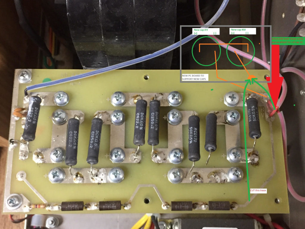
The modification involves adding two capacitors in series with the existing capacitor chain, with a bleeder resistor across the terminals of each capacitor. I’ve done this by constructing a small PCB that I’ve added to the amplifier. Then, move two HV wires, cut a HV trace and add a jumper for the metering, and add a jumper to complete the HV series circuit.
Conceptually, this is the modification. I’ve omitted the additional bleeder resistors on the drawing, but they are required!
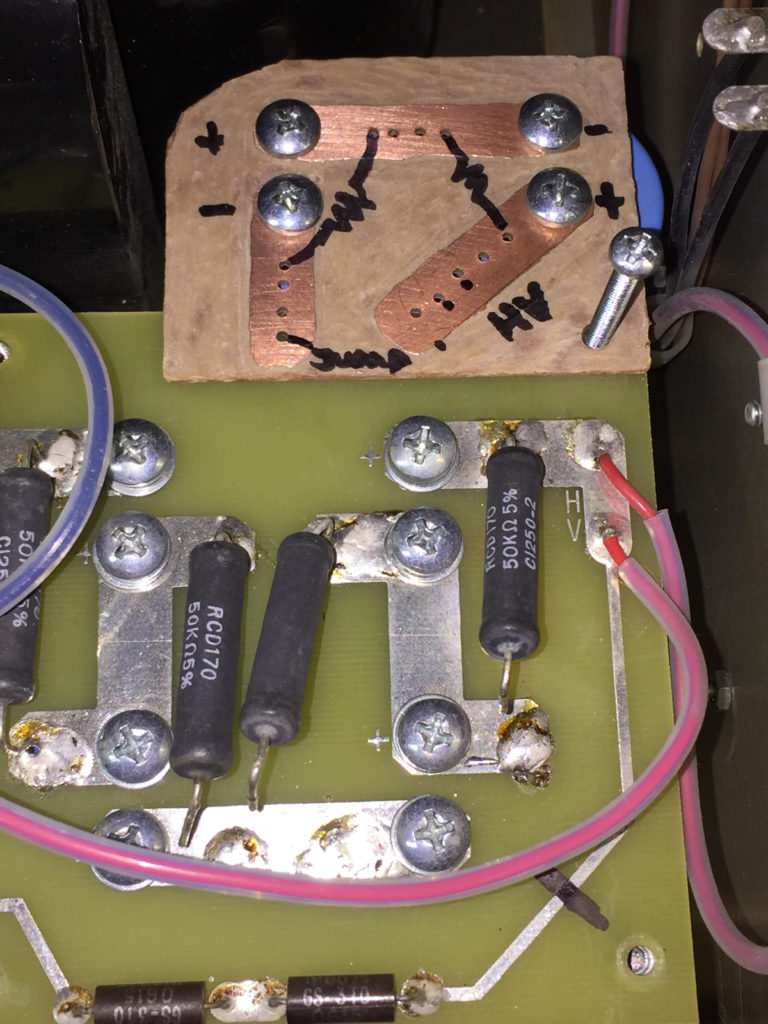
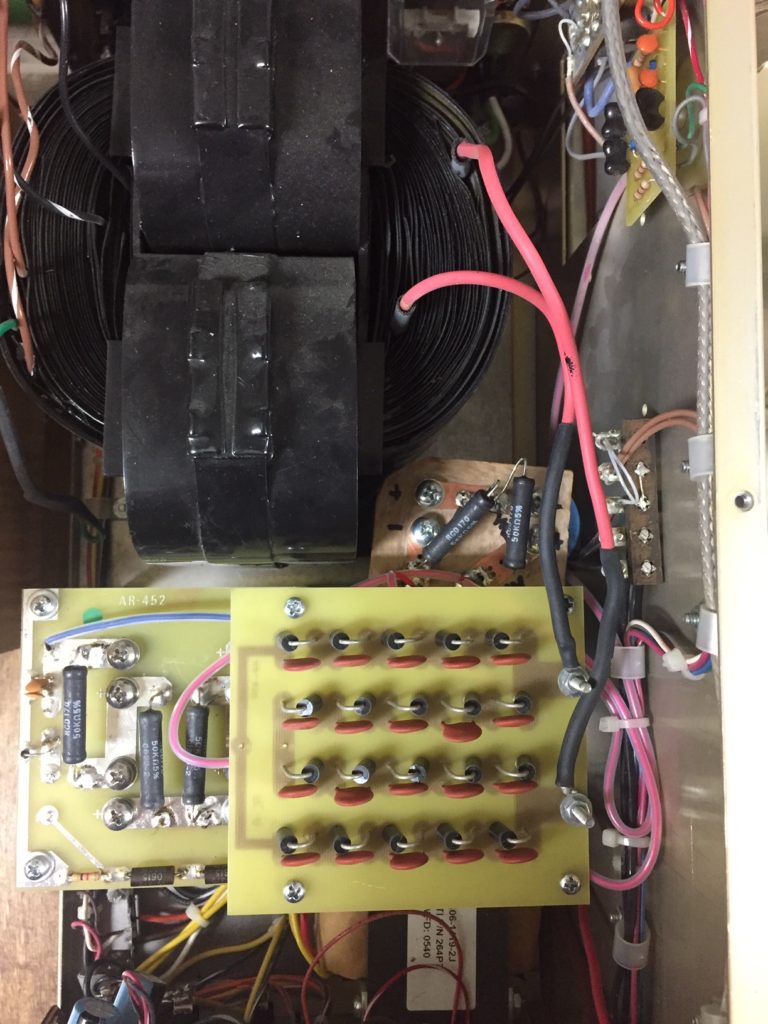
The existing bleeders are desoldered on one end to allow me to test them. The one on the far left had failed completely open, thus causing the capacitor to “tick”. That’s what has led to this modification. I had replaced all the caps and bleeders only five years ago.Here’s my first test fit of the additional PCB. Note the markings on the board indicating the bleeder resistors, capacitor polarity, jumper to complete the series circuit, and destination for the 2 HV wires to be moved, and the new HV metering jumper.The completed modification and reassembled amplifier.
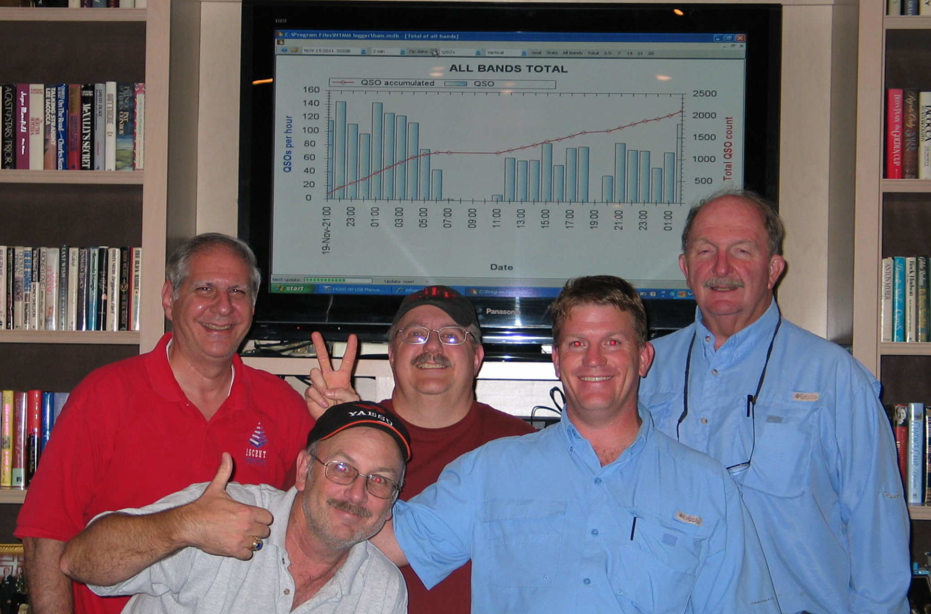
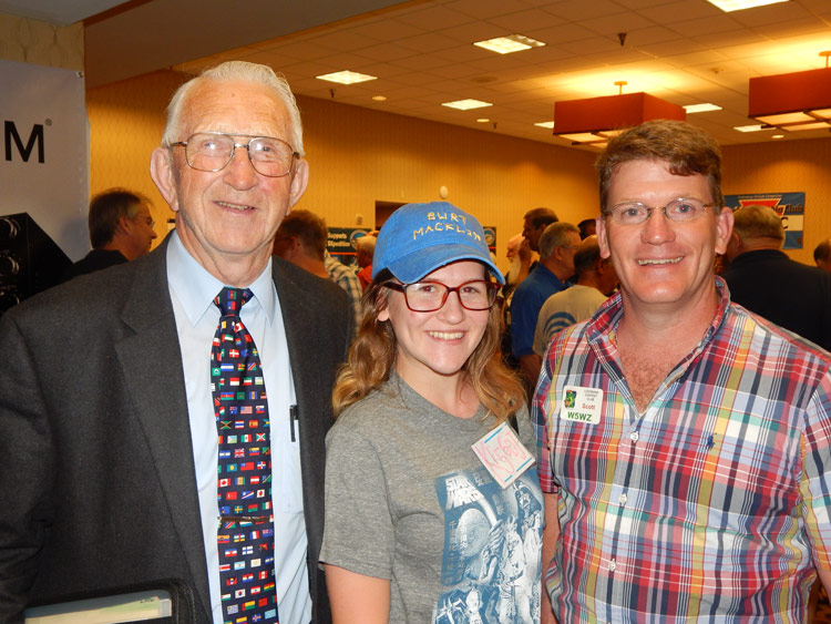
“10/31/2018 – Paul Bittner, W0AIH fell 60 feet from the Strum tower (40m). (It was) a beautiful day and he wanted to get ready for SS SSB. No services information yet obviously and the shock has still hit me. Please pass the word. Thanks.”
I last saw Paul at Dayton 2017 with my daughter Jordan KF5GDJ. K8CX took a great photo of us. He was a kind man, always pleasant to be around.
–Scott, W5WZ
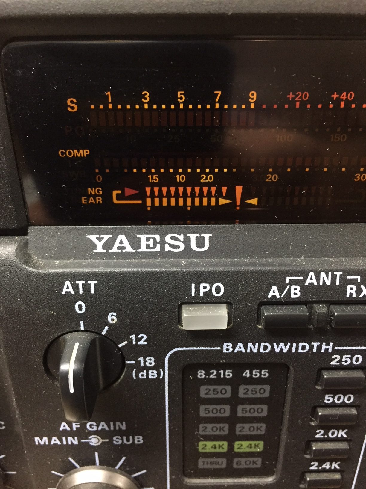
Recently, one of my FT-1000MP exhibit an odd thing on the display tuning bars. Notice the leftmost letters don’t display. The bars stay like this in all modes, both receive and transmit.
Failed Display Unit in FT-1000MP
The Yaesu guy, WA4GEG suggested replacing the entire Display Unit.
About 7 years ago, I bought an ‘MP for parts. Luckily, it still had a working display unit.
Earlier this evening, I made the swap. It took about an hour start to finish. Once again, I have two working ‘MPs.
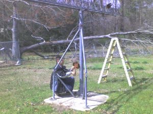
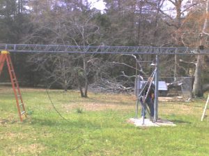
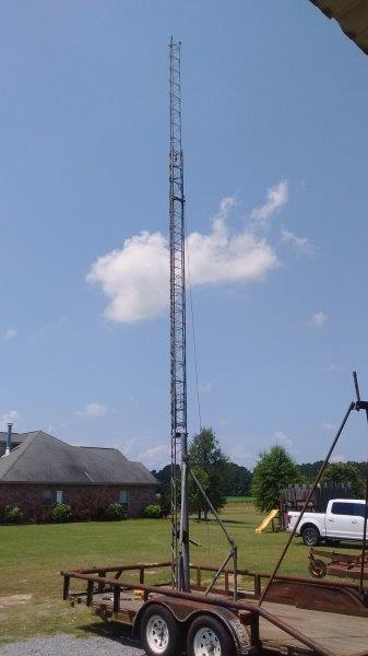
Several years ago I acquired an unidentified tilt-over crank-up tower. Manual winches, it appeared to be about 60 feet tall. The deal was take it down and it is yours. So it has sat behind my shop for about 10 years.
Recently, I saw a picture on the internet of an identical tower, and it was identified as an EZ Way, not that it mattered much to me at the time. However, the motorized trailered tilt-over crank-up tower that our club has used for Field Day for many years isn’t available this year. Ah-hah! Now I have a reason to be interested in the EZ Way. Of course, it was designed to be ground mounted. But I have a heavy trailer, and began considering the possibility of mounting the tower, temporarily and safely, on the trailer.
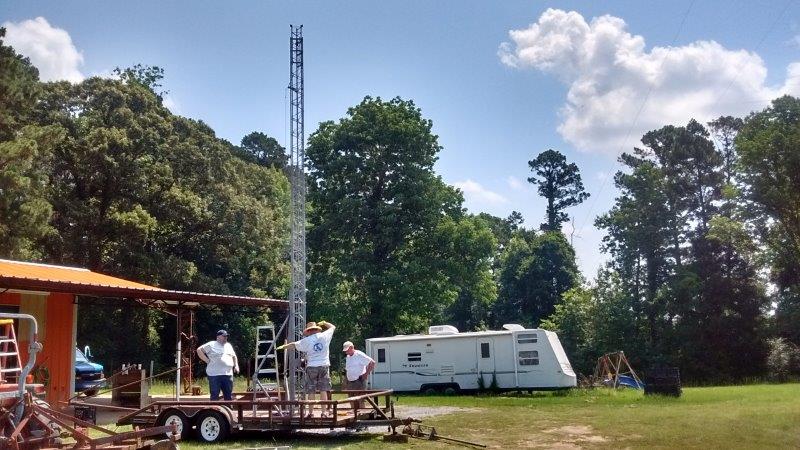
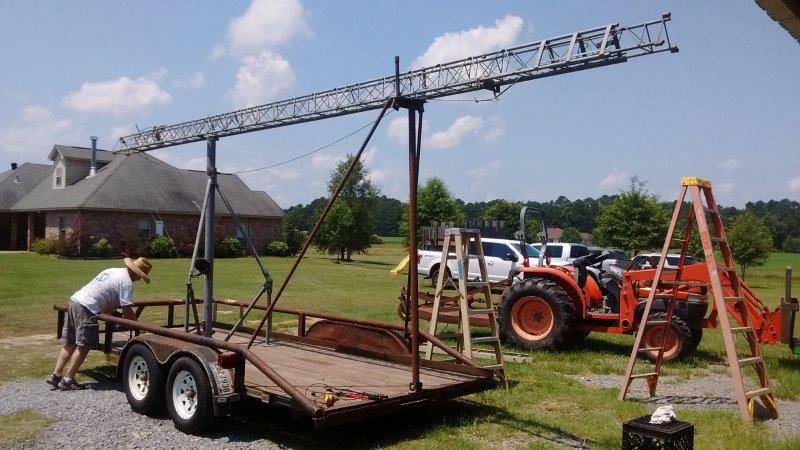
Short story is I reinforced the under frame at the four anchor bolt points for the tower base, and also fabricated a support for the long end of the tower to rest on when in transit.
All attachments to the trailer are bolted, so the installation is easily reversible to return the trailer to normal utility use. The project turned out quite nice!
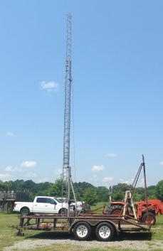
For FD, I don’t expect to need to crank up to more than 45 feet. Exercising the KISS principle, I’ll install a flat top plate with a 3 ft pipe stubbed up. Then, I can slide the larger diameter mast over it, and rotate it by a pull rope attached to one end of the boom. The antenna will be a KT-34.
Many thanks to Jim W5LA, Mark K5MSB and Shawn WA5VQP for the helping hands on the labor to make this all possible.
In 2020, I removed this tower from the trailer and installed it on a homemade Wonder Post.
During 2017 ARRL Sweeps SSB, we noticed that one of the FT-1000MPs had gone deaf on the receive antenna. During SS, this radio was on 40/15, so not having the beverage receive antennas available was not critical.
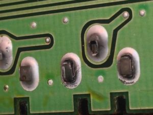
So, the night following the contest, I popped the top cover off, and removed the RF board. It only took a couple of seconds to identify 3 broken solder joints that hold the RCA connector on the board.
Broken solder joints on RF board, FT-1000MP, receive antenna input
Within 15 minutes, the connections were repaired, the radio reassembled, and tested on the air. Easy fix!
Back in Feb 2015, I noticed that my top rotator would not work from the control box in the shack. Troubleshooting and testing led me to the conclusion that the pulse counter reed switch in the positioner had failed. Continue reading “Upper M2 Orion 2800 Positioner Repaired!”
01/08-09/11 — Weather forecasts had a winter storm/ice storm warning for our area. The predictions were bleak. The actual event for my QTH was negligible. At ground level, perhaps 1/4″ radial ice accumulation. At this location, we dodged a bullet.
12/04/10 — Constructed an Inverted-L for 160 meters. Vertical component is 75 ft and horizontal is 100 ft. It is attached to Tower #1 at the 75 ft standoff, and the horizontal runs due north toward a tall pine tree. It is grounded to the same radial field used for the 80m shunt fed tower.
11/04/10 — Installed the final 2 coax filter stubs: a CS-1 on 80m and a CS-9 for 160m. Here’s what the installation looks like in the antenna switching shed.
Coax Stub Filters installed at SixPack on antenna ports:
10/23/10 — More work on stub filters. Added CS-3 and CS-7 to 40 meters.
Tested to determine cross-band interference. I used the lower C51XR for all 10, 15, 20 & 40 tests, and used both the 80m shunt tower and the 80m dipole on both transmit & receive. Transmit mode CW, power out 1.5kW. Receive mode CW, filters 6.0kHz.
Here is the matrix:
LEFT RADIO TX BAND
RIGHT RADIO RX BAND
10
15
20
40
80
160
10
X
<S0
<S0, avoid harmonic>S9+50
<S0, avoid harmonic>S8
nil
nil
15
nil
X
<S0, avoid harmonic>S8
nil, avoid harmonic>S9
nil
nil
20
nil
nil
X
nil, avoid harmonic>S9
nil
nil
40
nil
nil
nil
X
nil, avoid harmonic
nil
80
nil
nil
nil
nil
X
<S3, avoid harmonic >S9+20
160
nil
nil
nil
nil
nil
X
These results pleased me for first attempts at coax stub filters.
10/19/10 — Continued working on stub filters. Added CS-5 to 20 meters, and installed CS-6 & CS-4 to 10 meters.
10/16/10 — Found burnt barrel connector in top 20m antenna feedline (it had to be 120 feet off the ground). Replaced it and corrected the intermittent high SWR on that antenna.
10/06/10 — Tilted over Tower #3 and realigned the cubical quad to correct its heading. It slipped on the mast during a storm last year.
09/29/10 — Began building and implementing coax stub filters on the output of SixPack #1 to Tower #1. I have MUCH to learn in this area. Using an AIM4170, I cut two pieces of RG-213 to 1/4 WL at 7.150 MHz. One I made into a CS-3 and installed on the 15 meter port of the SixPack, and the other I made into a CS-4 and installed on the 20 meter port of the SixPack.
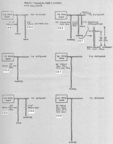
For reference, I’m using Managing Interstation Interference 2nd edition by W2VJN as well as K1TTT’s online Technical Reference and his online copy of K2TR Coax Stub filters article. I used the K2TR drawing, and cross-referenced it to the table on page 46 of Managing Interstation Interference . Here is the drawing, with the notations from page 46 superimposed.
Now I have to get more RG-213, more UHF ‘tees’, and spend more time learning and tweaking!